The Ford V-8 Engine Workshop
FE Block
332, 352, 390, 406, 410, 427, 428

1963 427-8V
FE Family
Bore Stroke
  3.30" 3.50" 3.78" 3.98"
4.00" 332 352 381 400
4.05" 340 360 390 410
4.13" 354 375 406 428
4.23" 371 393 427 447

Factory bore/stroke combinations are shown in bold

From somewhat humble beginnings as the 352 in 1958, the Ford-Edsel family evolved over more than a decade to give us such performers as the tri-power 406, the 427 introduced in March 1963, the 390 GT, and the 428 Cobra Jet introduced in April 1968.

Be sure to see the 427 SOHC article!

FE cutaway

390 intake manifold and crane At 650 lbs, the FE block engines are quite heavy. The intake manifold extends under the valve covers. Replacing the stock cast iron manifold with the aluminum version found on the 428 Police Interceptor (C6AZ-H) trims 55 lbs. off the engine. Here, a hoist is being used to lift off the old cast iron intake manifold. Watch your back!

1964 Galaxie 427-8V
1964 Galaxie 427-8V
Equipped with two Holley 4150 carburetors and cast iron headers, the 427 was conservatively rated at 425 HP @ 6000 RPM.
427 8V cutaway

410 and 428 engines are externally balanced. Due to different piston weights, there are actually four different 428 crankshafts. One used for normal 428, 428 Police Intercepter, and 428 CJ before 12/26/69. One for 428 CJ after that date, and two for 428 Super Cobra Jet before and after that date. All other FE engines utilize an internally balanced crankshaft. High performance 390 and 406 engines have grooved main bearing journals for improved oiling. 428 CJ article

FE Cross-bolted main caps Beginning with the 406 in 1963, high performance FE blocks featured cross-bolted main caps to provide endurance for high speed operation. Originally designed for the 427 SOHC, and introduced in 1965, the best FE block is the side oiler. This version feeds oil to the main bearings directly from a large oil gallery running along the bottom left of the block. Except for the 1968 model, these blocks do not have oiling provisions for hydraulic lifters. Side oiler blocks all feature cross-bolted mains and screw-in freeze plugs.

427 side oiler block rear face 427 side oiler block
The main oil gallery runs along the side of the 427 block. Oil enters the passage from the oil filter housing near the front of the block and runs its full length. Drilled passages intersect the main gallery to feed oil to the main and cam bearings at each main web. Pipe plugs used to cap the drillings. Also note the screw-in core (freeze) plugs.
427 side oiler relief valve
An oil pressure relief valve is found inside the rear of the block along the driver's side. The passage associated with this valve as well as the main gallery are pluged on the rear face of the block.

427 side oiler cross bolts 427 side oiler cross bolts
Due to manufacturing tolerances in the machining the block and main caps, each of the cross bolt spacers is custom fitted to its location. And they are a tight fit. The spacers are marked 2L, 2R, 3L, 3R, 4L, and 4R, to indicate main cap positions 2 through 4, left and right. For service replacement these spacers were sold in red, blue, and yellow sizes (0.3767", 0.3750", and 0.3733" thickness) for a selective fit. That's a 0.0017" jump from one size to the next.

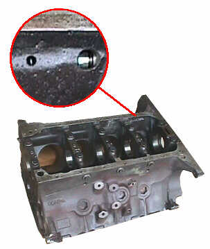
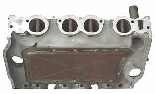
Ford made four different cylinder head and intake manifold setups for the 427. These are the low riser, medium riser, high riser, and tunnel port. "Riser" in this context refers to the height of the intake manifold above the head. The higher, the more direct the path from carburetor to intake valve.

The first 427 head was the low riser. These were a holdover from the 406. Intake ports measured 2.34" x 1.34". These featured 2.04" intake valves and 1.66" exhaust valves. In March 1963 the intake valves are enlarged to 2.09". Then for 1964 a minor modification was made just below the intake valve seat. A venturi like ring was added to improve flow. This was then used on all subsequent FE heads. This basic casting with revised exhaust port bolt patterns and Thermactor provisions was later used for the 428 CJ.

Developed next was the high riser. Very tall 2.72" x 1.34" intake ports and a matching intake manifold placed the carburetor high up above the ports with a clear shot to the valves. This combination was the reason for the teardrop hood bubbles found on Thunderbolt Fairlanes and lightweight Galaxies. Exhaust ports were slightly larger at 1.86" x 1.30". Intake and exhaust valves sizes were up, too, at 2.19" and 1.73" respectively. The valves were made of special alloy to be very light, and had tulip shaped heads in an effort to improve flow. The combustion chambers were fully machined.

NASCAR outlawed the bubble hoods. This lead the engineers back to the drawing boards resulting in heads. In 1965 the medium riser was released. This had much smaller intake ports, 2.06" x 1.38" but with better internal design that flows almost as well as the high riser. The valves are are the same as the high riser but are spaced farther apart in the chamber to accomodate the altered path of the intake ports. Slightly different valve train components are required. The medium riser is the best head for all around high performance use.

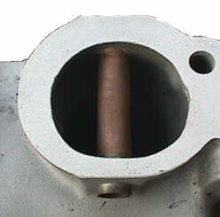
The last of the heads is the tunnel port, so called because the pushrod runs through a tube, or tunnel, passing right through the middle of the enormous intake port. The ports were nearly round, measuring 2.17" x 2.34". The intake valves were again made larger, 2.25". This same idea was tried for Trans Am racing in 1968 with the Tunnel Port 302.

Quite a bit different from the restrictor plate engines running in NASCAR today.

427 Tunnel Port pushrod tube
427 Tunnel Port intake, top 427 Tunnel Port intake, bottom

Modified: