|
|
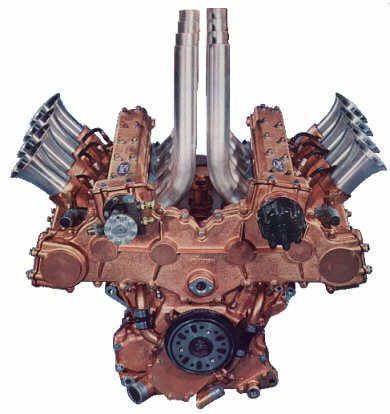
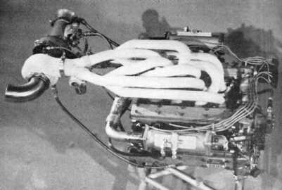
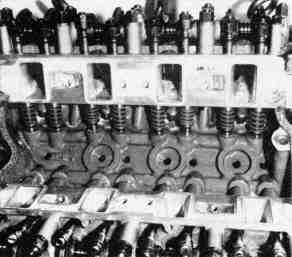
| The 1963 Indy pushrod engine produced 375 BHP at 7200 RPM from 255 cubic inches | |
|
Ford powered Lotus cars were prepared for Indy in 1963, to be driven by Dan Gurney and Jimmy Clark.
The engine for these cars was designed and built by Ford beginning in the fall of 1962.
Bill Gay, Executive Engineer of Advanced Engines, assembled a team of engineers including
Joe Macura and Richard Chen. Their objective was to build a racing engine of 255 CID,
producing at least 325 hp, and weighing no more than 350 lbs. The competition the was
Meyer-Drake Offenhauser. Ford purchased an Offy and tested it in one of their dyno cells.
It produced 400 hp at 6000 RPM. The team had their work cut out for them!
The design project was divided into two phases. First, to baseline the 260 Fairlane engine that was to be the basis of the new engine. Second, to develop a reliable aluminum version of the engine. Work on the 260 began on Sept. 1, 1962. The high performance 260 used in the Cobra was the starting point, dubbed the Stage 0 engine. Stage 1 involved revised and enlarged intake and exhaust ports, and 12.5:1 compression through the used of forged pop-up pistons. The special intake manifold carried four 46mm downdraft Webers carburetors. Larger valves, hollow-stemmed intakes and sodium-filled exhausts were fitted to the heads, along with high silicon content aluminum alloy retainers. 7/16" screw-in rocker studs, with Loctite and further secured by roll pins. The connecting rods were taken from the 289 HiPo engine, fitted with bronze wristpin bushings, shot-peened and polished. The crankshaft used cross-drilled journals for improved connecting rod bearing lubrication at higher engine speeds. After several different camshaft grinds were tried, the 260 produced 325 hp on gasoline, meeting the power objective set for the Lotus racecar. |
|
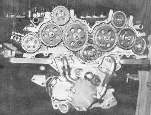
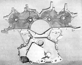
| Work on the aluminum Stage 2 engine began on Nov. 1, 1962. The sand cast aluminum cylinder block differed considerably from the production cast iron 260/289 block. The front of the block and timing cover were completely redesigned to support a gear driven camshaft and water pump. Due to the softer aluminum, the deck thickness was increased 50% to 0.64 inches. Bolt holes were lengthened to a thread engagement of 2 X bolt diameters. Main bearing caps were wider and held by 4 bolts. Cylinder heads were attached by studs, using six per cylinder. Four addition studs protrude from the lower edge of the block, and four studs aim down from the heads themselves into bosses at the edge of the lifter valley. | |
|
|
|
The bore size was changed from the 260's 3.80" to 3.76", resulting in 255 cubic inch displacement.
The block was fitted with dry cast iron sleeves, pressed in. The tops were grooved to
carry a steel O-ring gasket. Oil and water passages were sealed with rubber O-rings
and a bead of sealant ran across the lifter valley. This dry deck arrangement was
later used on the Boss 429. All torqued down, there was a slight
air gap between the deck and cylinder head, concentrating all the clamping loads on
the cylinder sleeve O-rings.
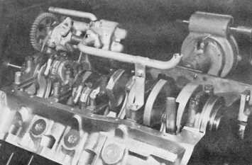
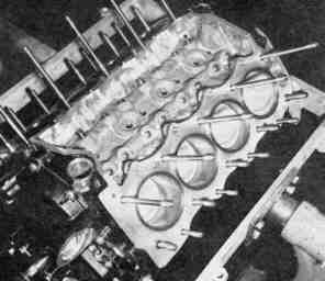
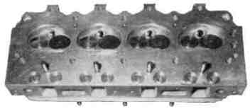
Special aluminum cylinder heads were made up using the 260/289 production head as a starting point. These heads used aluminum bronze alloy valve guides, alloy steel valve seat inserts, steel valve spring seats, oil passages for the shaft mounted Y-block style rocker arms, and four additional bosses to hold the top row of head studs. The production cast iron crankshaft was not up to the rigors of Indy. The racing engine used a forged steel crank, with revised counterweighting for internal balancing. Bearing size and type was identical to the 289 HiPo, tri-metal Clevite. The rod crank pins were drilled to lighten and and formed an oil reservoir. The ends of the holes were plugged with steel cup plugs, and pinned. This is similar to that found later on the 427. Forged pistons were used, with full-floating pins retained by double-helical spring retainers. Rods were taken from the Stage 1 engine, 289 HiPo, shot-peened and polished. The oiling system was highly modified and is explained below in the article on the 1964 engine. |
|
|
|
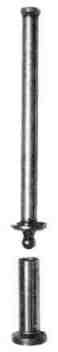
| The valve train received extensive redesign. Small diameter tappets weighing only 2/3 that of the production parts ran on the 340 degree duration camshaft. Overlap was 124 degrees. Lift at the valves was .510 inches. The hollow tubular pushrod featured a small cup on the top end to mate with the lash adjustment screw. The tappet end had a compbination spring seat and steel ball. The engine used a revkit, springs fitted under the heads applying pressure against the tappets directly. This reduced loading on the rockers and valve springs and helped improve high speed valve control and longevity. Due to the high coefficient of thermal expansion inherent with the aluminum components, valve lash was set at .032 inches cold. | |
|
|
|
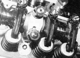
At high speed the stud mounted rockers
were found to oscillate, throwing off valve events and often failing outright.
The stud mount ball type rockers were replaced by a shaft-mounted system taken
from the Y-block. This system was later used on the Tunnel Port 302.
Dual springs, with an inner and outer coil were used and fitted snugly together,
rubbing, to help dampen harmonics.
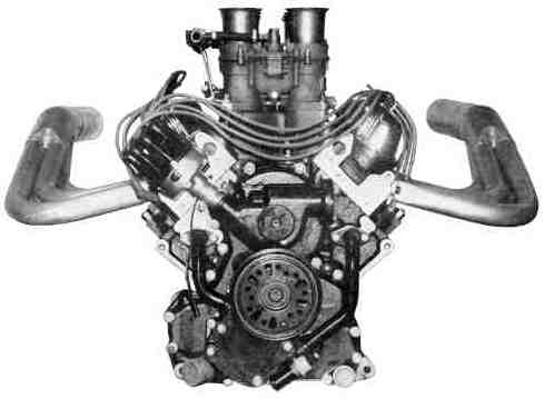
The Stage 2 got a new intake, this time fitted with 58 mm Webers. Ford tested the engines and did some of the tuning work using a 1963 Galaxie. This chassis with a very low rear axle ratio allowed the engineers to simulate the full throttle acceleration runs typical of the Indy racetrack. From a lower rpm limit of 5000 rpm to the maximum of 7200 rpm at the end of the long straights. With the body removed from the chassis, Ford placed the "car" in its windtunnel to streamline the exhaust headers. The Autolite Division prepared an electronic spark box for the engine. No mechanical advance was used. The static timing was set to 50 degree BTDC! Due to delays in the electronics of about 1 degree per 1000 rpm, the final spark timing was 43 degrees at 7000 rpm. (I wonder how that started the darn thing?) The project was completed in time for the Indy time trials in May, 1963. The engine was producing 365 hp. The test engine had run 2-1/2 hours on the dyno, and over 450 miles on the track at Indy. It was returned to the dyno and found to have broken in a bit, producing 376 hp. |
|